Building my first (working) dipole antenna
I’m super pumped about building my own antennas. There’s something magical about turning a carefully measured and cut length of wire, into hardware that can reach someone miles away. It feels so good, man. And this craft is niche, even for engineers, and I’m excited to build the skills needed to earn my place amongst its dark wizards.
The very first thing I ever tried was a dual-band Yagi antenna to work the repeater on the space station, but man that was not the right starter project. I will post about it when I make it work.
Antenna building requires many little details to be done just right: materials, sizes, lengths, connectors, you name it. Every choice will determine whether you end up with an antenna that will work at all, or merely an interesting-looking piece of metal, let alone one that works well.
So, after the confusing failure with the Yagi, I put it on the back burner and looked for something more attainable. I settled on a center-fed dipole antenna for the 2m band. It is simple, compact, and forgiving enough, but still challenging enough to teach me something.
Scaling back
As always, I went a little bit too far too fast. I bought some aluminum rods from the Home Depot and fired up the computer to CAD an articulated hub for a stowable antenna. After a bit of thinking I decided to pull back the scope and start with an even simpler version: a dipole made with two lengths of electrical wire.
Antenna design
I’m building a center-fed, half-wave dipole for the 2m band. It is designed to be mounted vertically for vertical polarization. This configuration should give me good performance for the local 2m repeaters and simplex.
To calculate the length of the wire segments I went with the basic formula \(\lambda = \frac{c}{f}\)
I want the antenna centered on 146.52 MHz (simplex calling frequency for 2m), and assuming $c \approx 300\ \text{Mm/s}$ this gives a length of:
\[\lambda = \frac{300}{146.52} \approx 2.05\ \text{m}\]Since this is a half-wave, the total antenna length is $\frac{\lambda}{2}$ and each half of the dipole’s length is approximately $\frac{2.05}{4}\ \text{m} \approx 0.51 \ \text{m}$
So I started with that amount of wire on each side and expected to trim down once tuning with the nanoVNA.
I grabbed a couple of lengths of 12 AWG wire I had lying around in the shop. It’s quite beefy for an antenna like this, but it should help with bandwidth.
Making the antenna
I designed and printed a central “hub” to hold a panel mounted BNC connector and to provide some structure, fastening and stress relief for the wires.
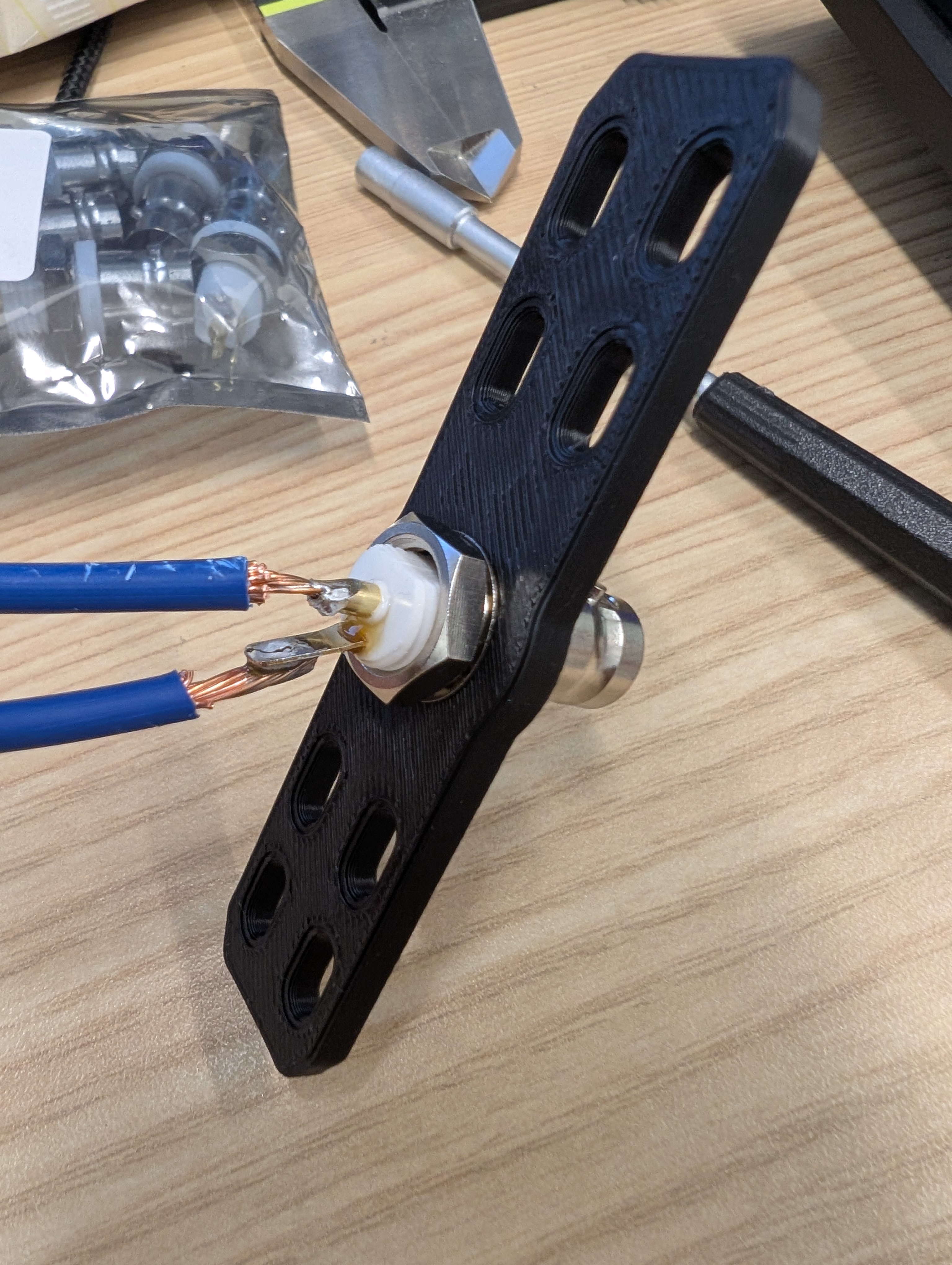
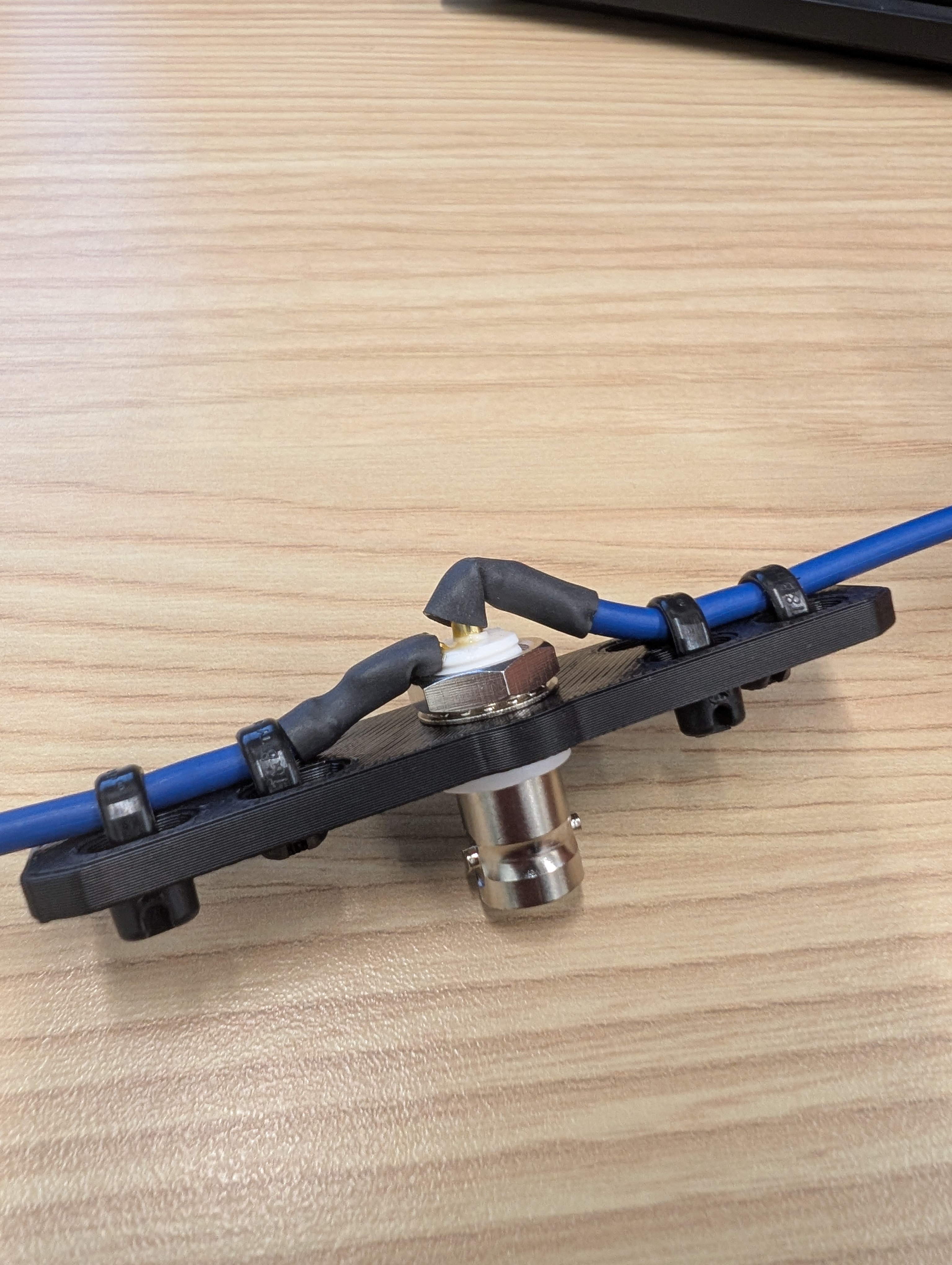
I soldered the wire halves directly onto the BNC connector. The heavy wire made the center connection tricky, so next time I’ll use something thinner and more flexible. I protected the solder joints with heat shrink, secured the wire halves to the hub with zip ties, and gave everything a firm tug test. Nothing moved, good to go.
This antenna needs to be installed in a vertical orientation, and since the wire is not structural and the antenna will rather need to be hung, I also printed two little clamps to perform as hooks and allow me to hang the antenna.
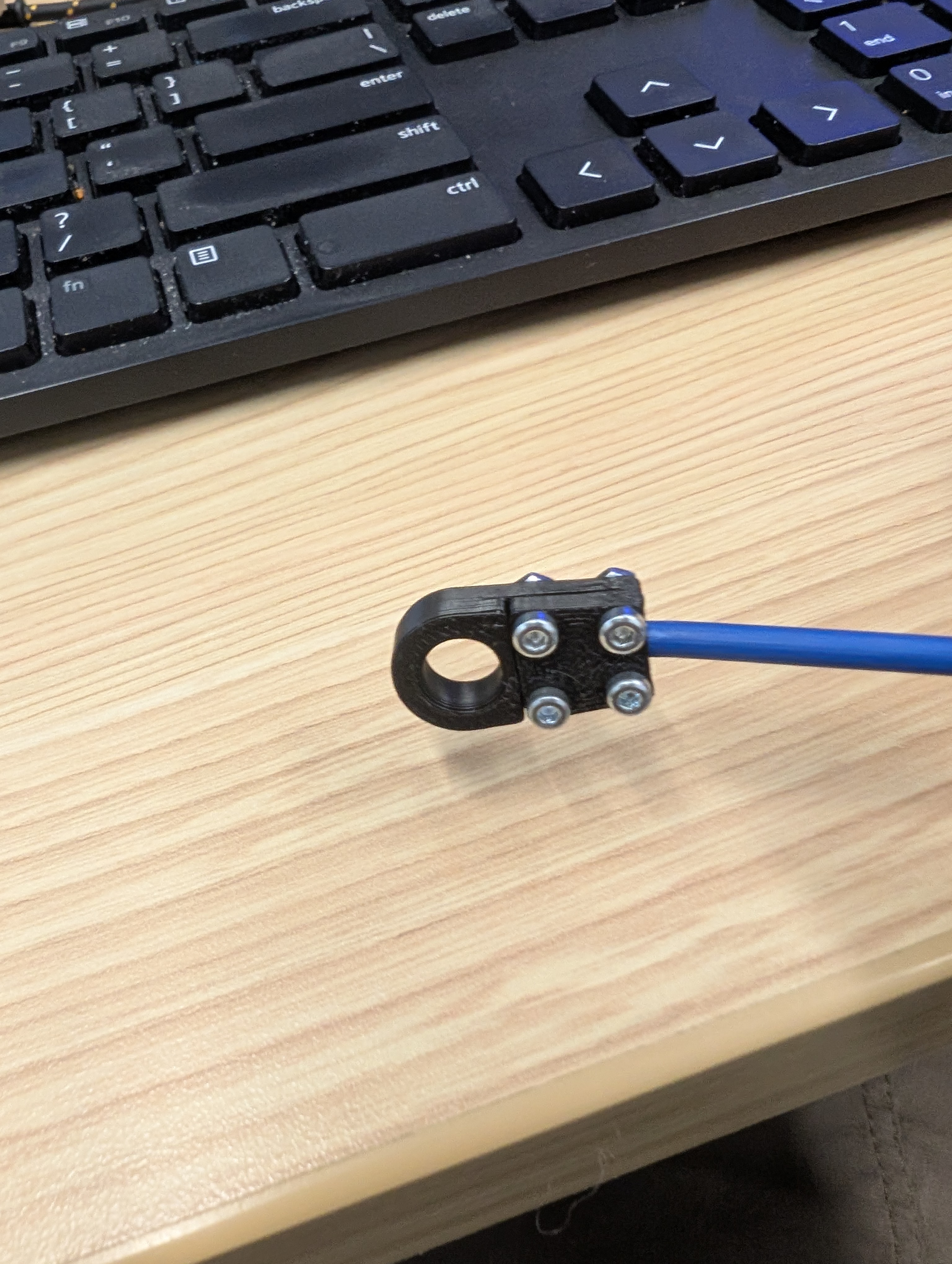
I added a channel for the wire so when the clamp is screwed together the wire is bitten by the clamps and they don’t detach. The clamps are made of PLA and the tiny M2 screws are not electrically connected to the wire, so there should be no significant effect on the antenna performance.
Time to test!
The nanoVNA
I have a relatively cheap nanoVNA I got from Amazon. I didn’t want to spend the big bucks just yet, so we’re yet to see if I need to regret any life decisions.
This was my first time actually using the nanoVNA for tuning rather than just to click around on the screen. Once I understood the workflow, I realized how useful a device this is.
The UI is convoluted though, and mine came without a manual. I relied heavily on ChatGPT while learning how to use this thing. Now I can measure how well the antenna performs and determine whether it’s safe to connect to my radio or not.
I think I’ll write a post on how to use it. Or maybe make a video or something. Anyway, time to test!
I hung the antenna near the center of my living room using painter’s tape and string, with the BNC connector at a convenient height. Because the antenna is so light, I didn’t need any fancy mounting solution. The pic below shows how my setup looked.
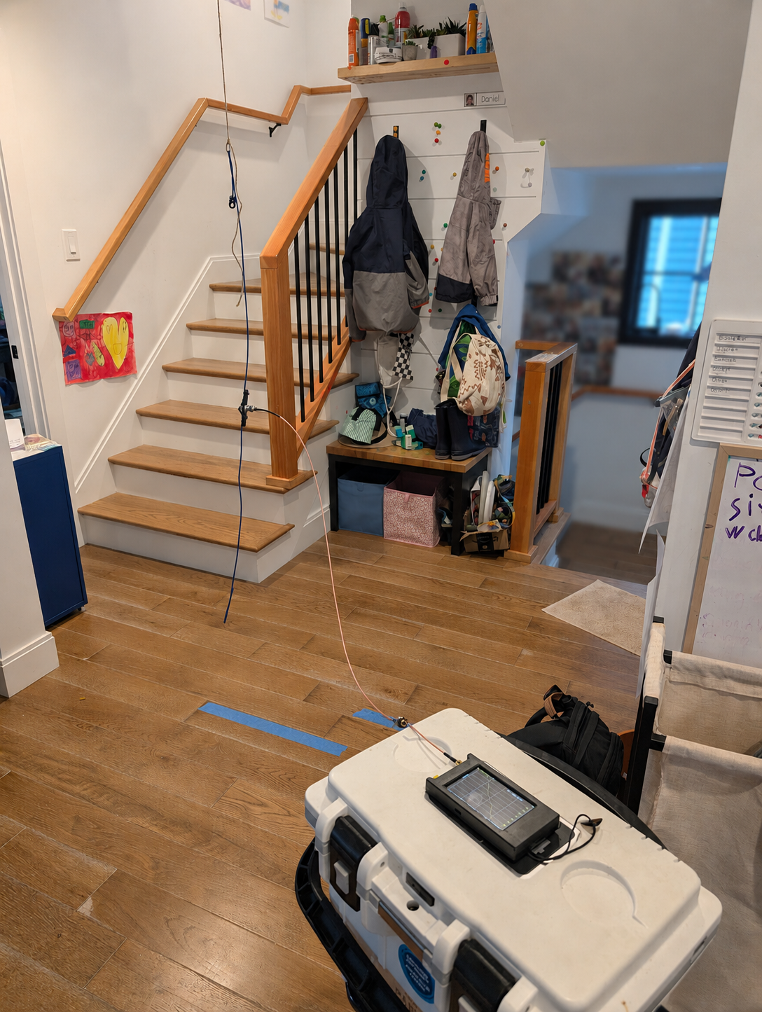
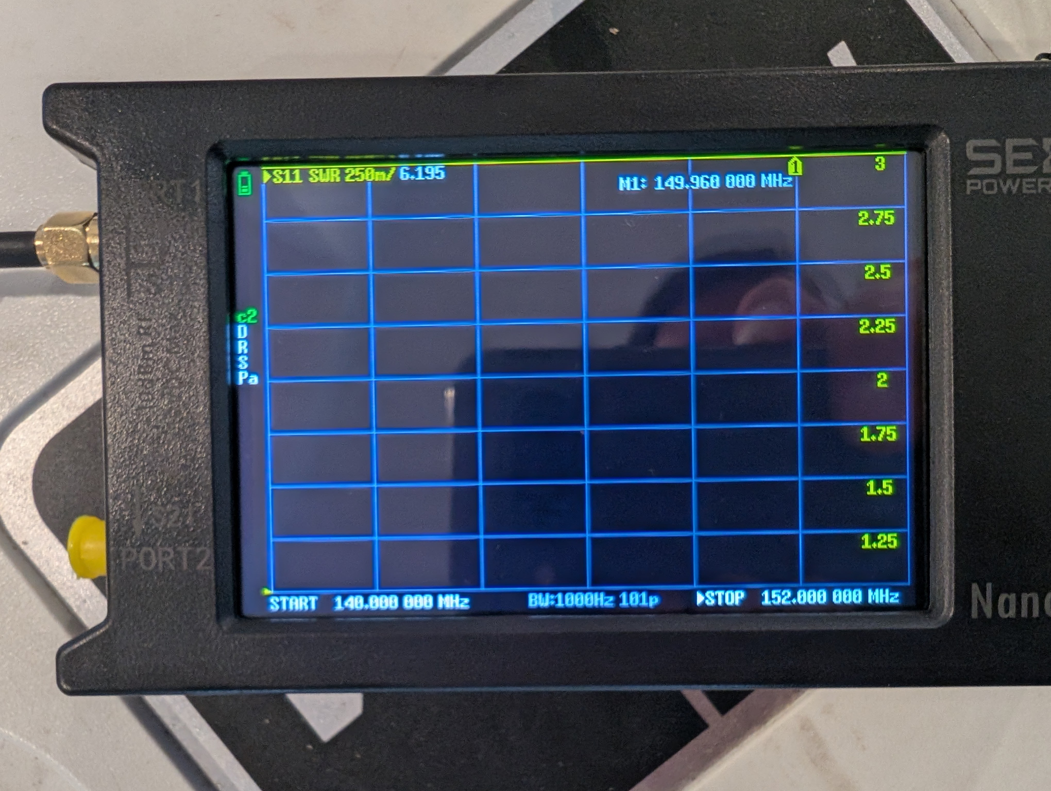
After calibrating the VNA with a 3’ coax jumper, I hooked it to the antenna and did a first sweep between 140 and 150 MHz, and saw a pretty bad SWR of roughly 6:1. I shortened the halves by folding the wire ends back on themselves. Folding the ends back reduces their contribution to the antenna’s effective electrical length, making quick iterations really convenient.
After a couple of tries, including widening the sweep from 110 to 150 MHz so I could see more of the antenna’s response, I finally ended up with a pretty decent dip at the right frequency!
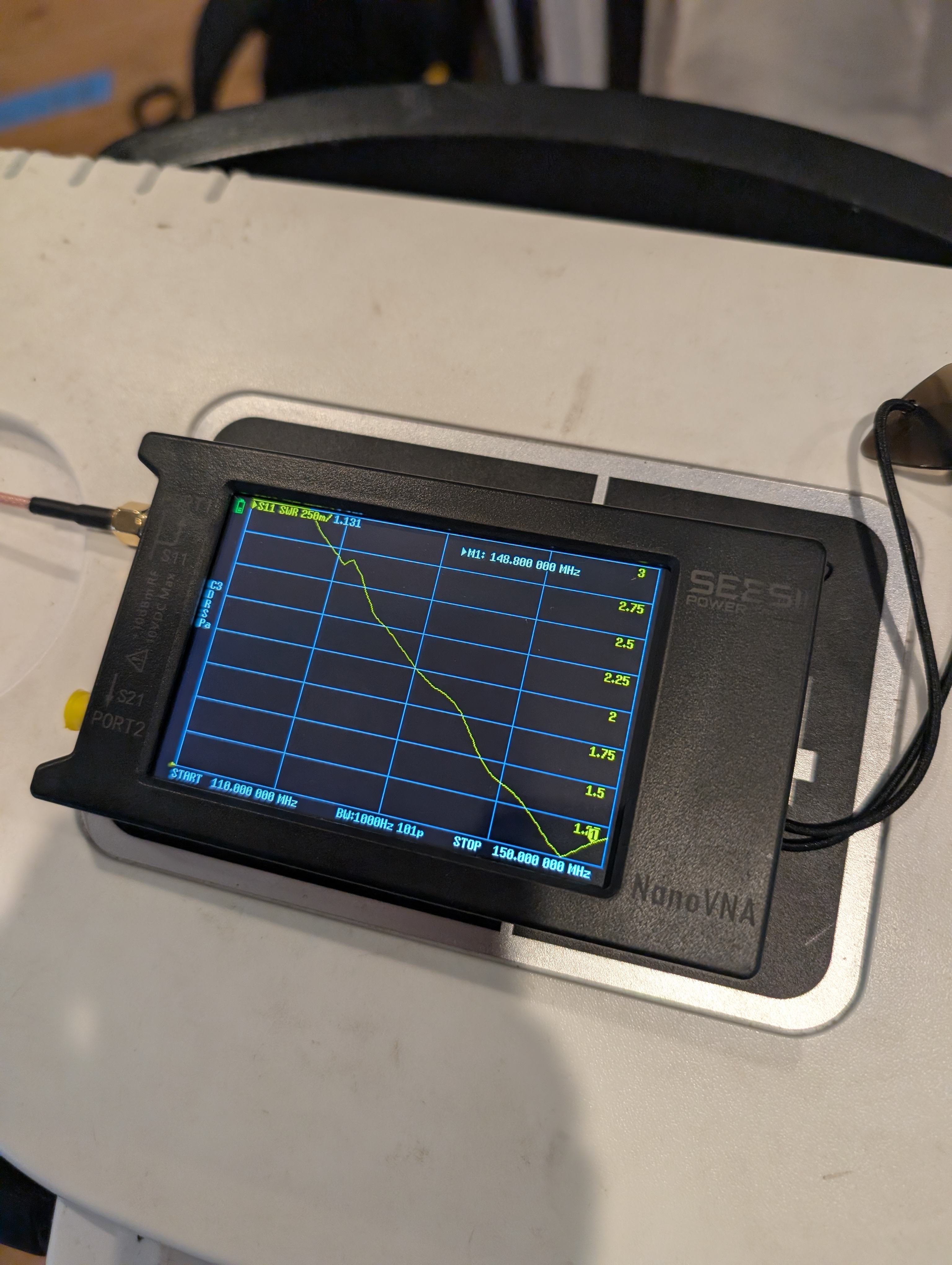
I had to step back each time I wanted the VNA’s reading to stabilize. That suggested the antenna was not fully balanced and the coax was interacting with it.
I tried coiling a choke with the coax, but I only have 3 feet to work with. The small coil made the reading a bit more stable, but also detuned the antenna a lot. I should get a set of Mix 43 ferrite beads.
Once I saw I had low SWR across the 2m band, I hooked up my HT (an AnyTone AT-D878UVII Plus), and tuned to the local W1BOS repeater and heard some activity, but I wasn’t able to open the repeater (no tail, no CW ID back).
I was a bit disappointed, but then decided to test it outside and it was a great success!
I called CQ on 2m simplex and made contact with a local ham N1OSG (Andy). He gave me a 59 report, and I received him with equal strength and clarity. I had worked his station before using the SignalStuff stick, but it had been noisy. I was really happy with the quality of that first contact!
Andy then helped me test the local repeaters and reported that my signal came through well. We worked the 2m repeaters but skipped the 70cm ones because the nanoVNA showed an out-of-range SWR around 430 MHz.
So, I built a pretty decent 2m dipole, not a dual-band dipole. Still, pretty good!
Lessons learned?
Yes:
- The nanoVNA is super useful. Learn how to use it well and efficiently
- The leads between the BNC and the radiating elements can actually form part of the antenna, so either measure them and add them to the element’s length, or make them as short as possible (less critical for the lower bands)
- The antenna is not fully balanced, so there’s some current flowing on the coax. Get some ferrites!
Future projects?
YES! I’m going to basically build the same antenna as I had originally imagined it, using rods instead of wires and adding pivot points to the hub so it is nicely portable.
73, KC1ZTY out.